Unique selling points
- No aeration energy for removal of organic carbon compounds
- Low sludge production and associated treatment efforts
- Chemical free process to remove methane from liquids
- Up to 99% methane recovered from the dissolved fraction
- Pathogen and solids free effluent which can be re-used in a number of applications (e.g. farming and industrial use)
- Compact equipment with low CO2e footprint
Description of the technology
The anaerobic membrane bioreactor (AnMBR) is usually applied as pre-treatment for wastewater with high organic loads. Hereby, organic carbon compounds are biodegraded to biogas, mainly consisting of methane (CH4) and carbon dioxide (CO2). It is a system with biomass accumulation, meaning that the hydraulic retention time is decoupled from the solids retention time and, thus, allows anaerobic microorganisms to proliferate without being washed out of the system (Lew et al. 2009). The AnMBR can be applied for industrial wastewater, such as in the project ULTIMATE and for municipal wastewater, such as in the project NextGen.
Jiménez-Benítez et al. (2023) concluded that a demethanistion of an AnMBR effluent is necessary to achieve an environmentally sustainable operation of an AnMBR. They recommend the combination of an AnMBR with a degassing unit.
As in the project NextGen at the case study in Spernal, a membrane contactor unit (MCU) has become reliable and efficient for recovering dissolved gases such as CH4 from the AnMBR effluent. This methane can be used as an energy source. The MCU employs a microporous hollow fibre membrane, which is the most used configuration for MCU due to its high gas-liquid separation efficiency and very high surface area as compared to flat sheet membranes.
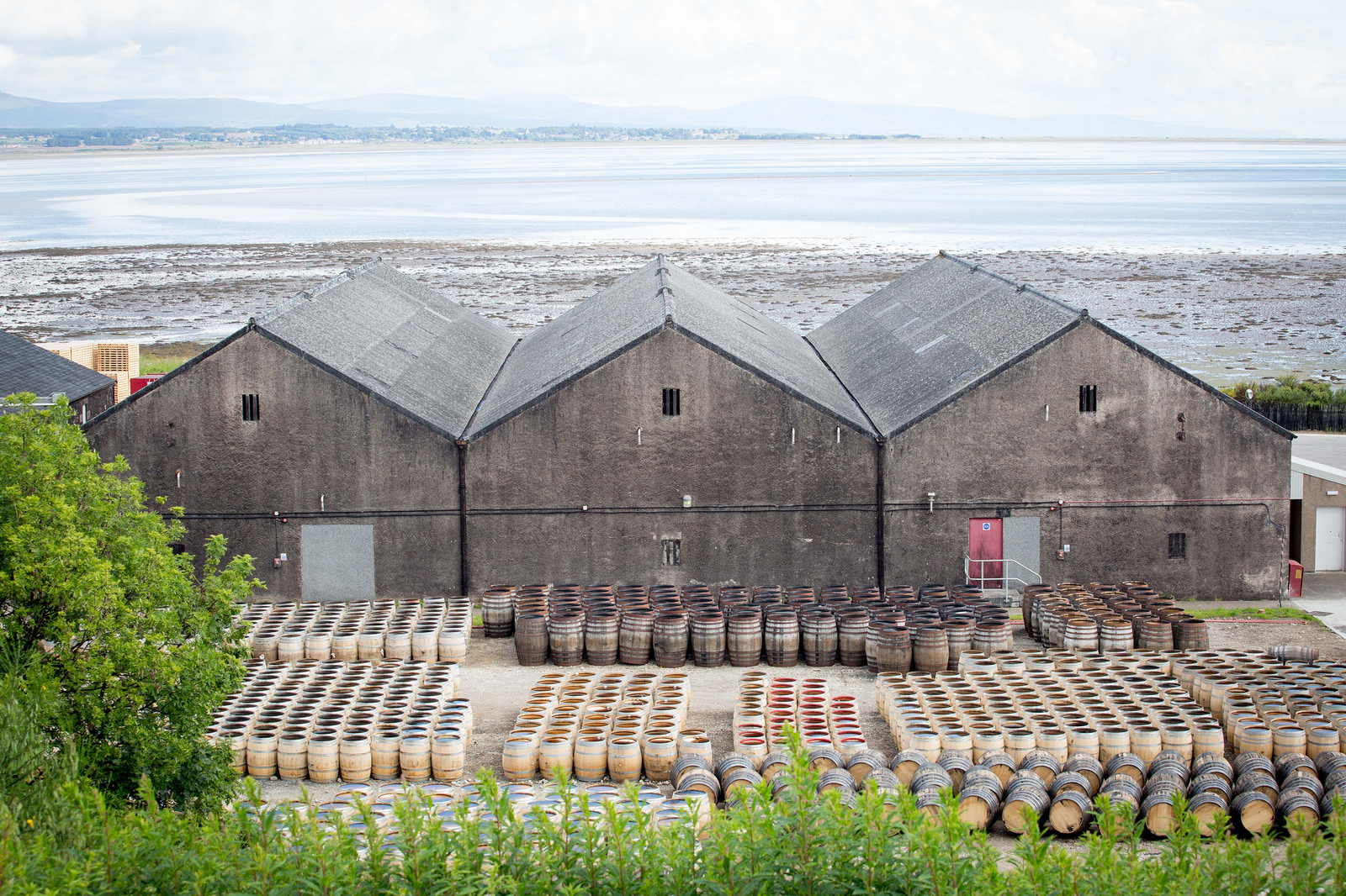
In the project ULTIMATE at the case study in Lleida, an AnMBR is combined with the electrostimulated anaerobic reactor (ELSAR) technology and located downstream of the ELSAR system to produce fit-for-purpose water at pilot-scale. Both systems pre-treat brewery wastewater. At the ULTIMATE case study in Tain, the AnMBR is used as the main treatment technology to remove the organics (>98%) from the distillery wastewater while polishing of the effluent with nutrients recovery technologies is investigated.
Flow scheme of the technology
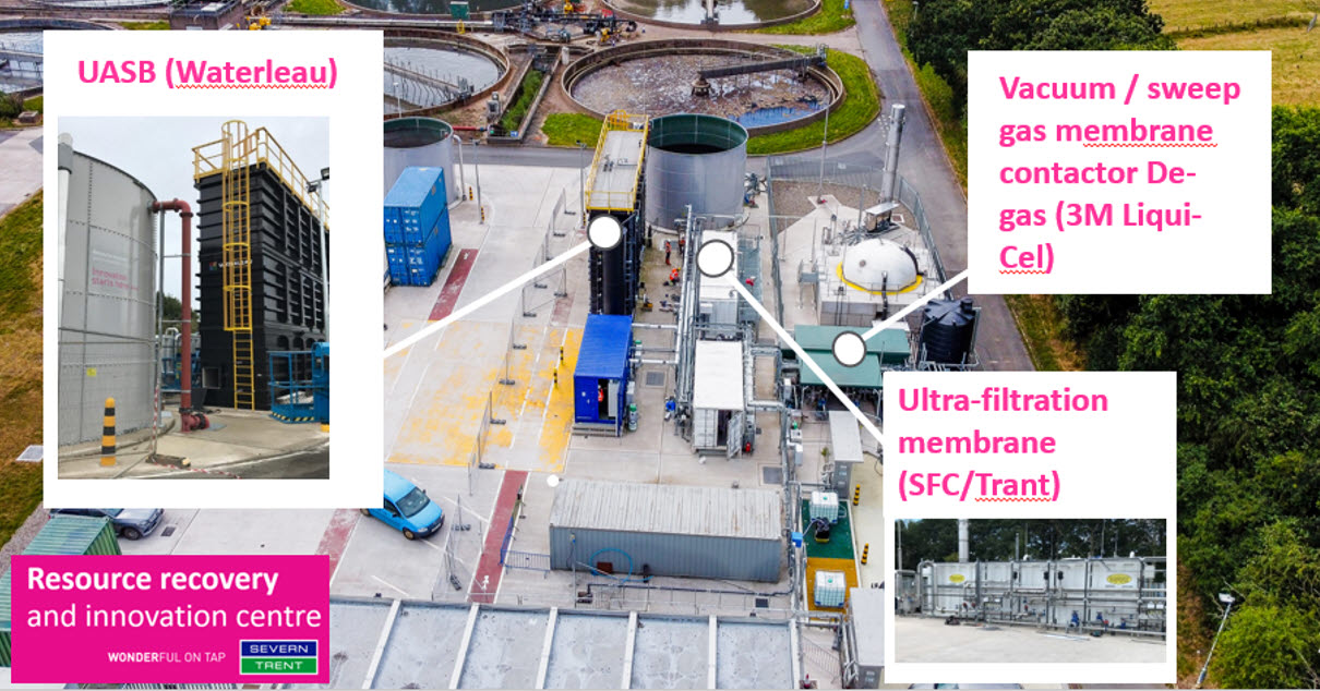
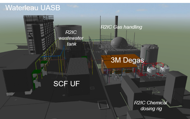
The AnMBR combines a bioreactor with either flocculant or granular biomass, such as an up-flow anaerobic sludge blanket reactor (UASB) with physical separation membranes, ultrafiltration (UF) for solid-liquid separation and membrane contactor for gas-liquid separation. As shown in Fig. 1, the UF membrane system is integrated with an up-flow anaerobic sludge blanket reactor (UASB) in a side-stream configuration.
AnMBR
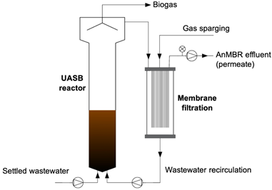
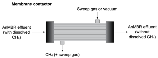
Fig 1. Example of the AnMBR of the case study Spernal in the project NextGen
In the MCU process, water passes through the outside (shell side) of the hollow fibres while a sweep gas (or vacuum) is applied to the inside (lumen side) of the fibres. Because the membrane is hydrophobic, it allows direct contact between gas and water without dispersion. Applying a higher pressure to the water stream relative to the gas stream creates the driving force for dissolved gas in the water to pass through the membrane pores. Then, the methane is transported using a vacuum pump or together with sweep gas to the biogas to generate electrical and thermal energy (Fig.1).
Pictures

Synergetic effects and motivation for the implementation of the technology
- Improvement of dewatering and reduction of dry matter
Excess sludge production in the AnMBR is very low, but still this need extracted from AnMBR from time to time, to avoid high solids concentration reaching the UF side-stream module. This excess sludge can be further stabilised in an anaerobic digester (AD) and dewatered, together with the primary sludge. This sludge still has a high CH4 potential, and the organic matter is converted into biogas leading to a further reduction in the total dry matter content in the digested sludge. As a result, transport and disposal costs can be reduced. Furthermore, the treated sewage solids (i.e. biosolids) can be successfully used for fertilisation of land and for landscape purposes.
- High quality product by combining with other conventional treatment processes
MCU is applied as post-treatment to the AnMBR effluent. MCU applications include removing biogenic hydrogen sulphide, carbon dioxide, oxygen and ammonia. Coupling AnMBR with MCU for wastewater treatment allows for the recovery of the dissolved methane, clean water rich in valuable nutrients. Under UK winter, up to 100% of the methane is found dissolved in the liquid phase, as wastewater temperatures are in the range of 6-8°C. CH4 has a high greenhouse gas potential, and its recovery and management are crucial to ensure the low environmental impact of the technology. The recovery of dissolved CH4 has an energy demand. For its coverage, green energy should be used to contribute to the low environmental impact (Remy et al. 2022).
Technology requirements and operating conditions
The more organic matter is biodegraded in the AnMBR, the higher the biogas yield is. Several parameters affect biogas production and the methane yield in AnMBRs, including hydraulic retention time (HRT), solids retention time (SRT), temperature, pH and organic loading rate (OLR).
Operating conditions of the AnMBR and degassing unit in Spernal
|
Parameter |
Units |
Min |
Max |
Reference |
|
AnMBR using an UF |
||||
|
Organic loading rate (OLR) for AnMBRs |
kg COD/(m³*d) |
1.5 |
25 |
|
|
Inlet TSS |
mg/L |
200 |
|
|
|
Outlet TSS |
mg/L |
≤ 3 |
||
|
Outlet Turbidity |
NTU |
≤ 0.5 |
||
|
Permeate flux (UF) |
L/(m²*h) |
10 – 25 - 50 |
||
|
Pore size (UF) |
nm |
20.1 |
||
|
Total Filtration Area |
m² |
1074 |
||
|
pH |
- |
6 |
8.2 |
|
|
Temperature |
°C |
4 |
25 |
|
|
Flow rate |
m3/d |
200 |
500 |
|
|
Hydraulic retention time (HRT) |
h |
8 |
10 |
|
|
Sludge retention time (SRT) |
d |
10 |
150 |
|
|
Degassing unit |
||||
|
pH |
- |
6 |
9 |
|
|
Temperature |
°C |
4 |
30 |
|
|
Pressure |
mbar |
2 |
60 |
|
|
Gas extraction driver |
Liquid ring vacuum pump technology and/or nitrogen gas |
|||
The feasibility of anaerobic wastewater treatment in the UK has been demonstrated through pilot-scale trials that have taken place at Cranfield University since 2003. Until now, the work completed to date has shown that treating municipal low-strength wastewater (COD <400 mg/L) at temperatures between 6-22°C, with an average of 14°C, is feasible. Furthermore, it has the potential to replace traditional energy-consuming aerobic wastewater treatment processes. Hydrolysis is the limiting step, emphasising the need to provide long sludge retention times to ensure stable biogas production and solids can be maintained in the reactor by using a membrane filtration after the UASB. This combined system has been investigated at pilot-scale (Soares and Vale 2022). Membrane fouling can be controlled by intermittent gas-sparing practices using biogas, while maintaining the energy efficiency of the process. The membrane operation can be turned up-down, enabling design at average flow rather than full-flow to treatment.
Key performance indicators
During the start-up phase, total chemical oxygen demand (tCOD) removal rates of 60-70% were achieved in Spernal (Soares and Vale 2022). Coupling the UASB with a membrane enables the production an effluent with no TSS content, a tCOD below 20 mg/L and aBOD below 10 mg BOD/L. This effluent meets the requirements for water reuse, according to the EU Regulation 741/2020 (without considering the microbial removal performance). In addition, tCOD removal rates between 90-95% are expected (Soares and Vale 2022). Lew et al. (2022) observed a tCOD removal rate of 88% for municipal wastewater, while Chang et al. summarized for industrial wastewaters rates between 90% and 99%. Methane composition in the biogas is high (80%), facilitating its upgrading or other uses. Conversely, nutrient removal in the anaerobic reactor is negligible (5-10% phosphate removal and ammonia increase by 5-15% due to solids hydrolysis). Post-treatment for nutrient removal/recovery is necessary.
|
Parameter |
Units |
Min |
Max |
Reference |
|
|
Removal efficiencies [%] |
Total COD |
% |
90 |
99 |
|
|
TSS |
% |
100 |
|||
|
Methane yield |
m³ CH4/(kg CODremoved) |
0.16 |
0.48 |
||
|
Methane removal/ recovery in degassing unit |
% |
99 |
|||
The sulphate content in the wastewater is a very important parameter because sulphate-reducing bacteria (SRB) being active under the anaerobic conditions reduce it to H2S using hydrogen and acetate as substrate (Lovley et al. 1988). Competing for the same substrate as the methanogenic archaea, the SRBs can even outcompete methanogenic archaea, reducing the methane yield. Furthermore, H2S can inhibit methanogenic archaea at a specific concentration. More information is provided in the factsheet about anaerobic digestion. Furthermore, the dissolved H2S degasses together with the methane in the degassing unit and can lead to corrosion processes.
Links to related topics and similar reference projects
|
Biogas Production |
Reference |
|
Anaerobic membrane bioreactor (AnMBR) |
Case studies "Spernal" (NextGen), “Tain” & “Lleida” (Ultimate) |
|
Enhanced biogas production due to thermal pressure hydrolysis |
|
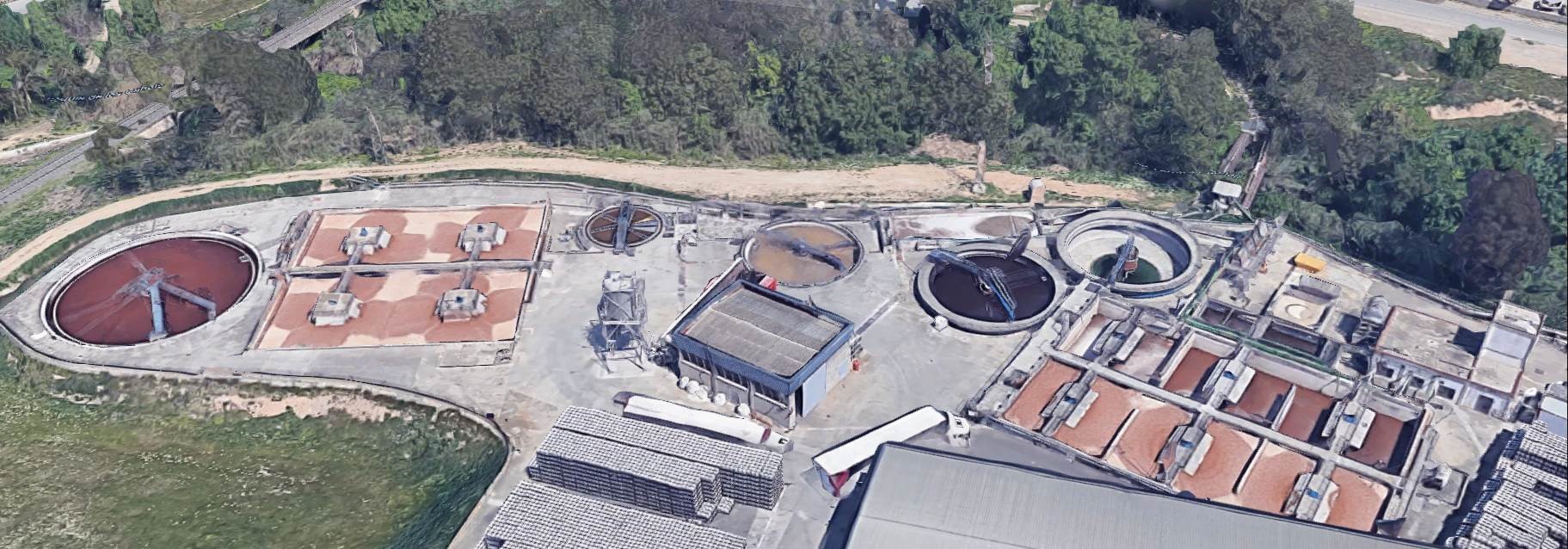
Case Studies applying the technology
Publications
- Chang, S., Anaerobic membrane bioreactor (AnMBR) for wastewater treatment, 2014
- Jiménez-Benítez, A., Ruiz-Martínez, A., Robles, Á., Serralta, J., Ribes, J., Rogalla, F., Seco, A., Ferrer, J., A semi-industrial AnMBR plant for urban wastewater treatment at ambient temperature: Analysis of the filtration process, energy balance and quantification of GHG emissions, 2023
- Kim, J., Hofman, J., Kenyeres, I., Poor-Pocsi, E., Kleyböcker, A., Heinze, J., Kraus, F., Soares, A., Paissoni, E., Vale, P., Palmer, M., Bloemendal, M., Beernink, S., Ros, S., Hartog, N., Frijns, J., D1.4 (2022) New approaches and best practices for closing the energy cycle in the water sector, 2022
- Lew, B., Tarre, S., Beliavski, M., Dosoretz, C., Green, M., Anaerobic membrane bioreactor (AnMBR) for domestic wastewater treatment, 2009
- Lovley, D., Phillips, E., Novel mode of microbial energy metabolism: organic carbon oxidation coupled to dissimilatory reduction of iron or manganese, 1988
- Plana Puig, Q., Nanu, C., Groza, I., Soares, A., Vale, P., Monokrousou, K., Makropoulos, C., Katsouras, G., Tsalas, N., Tazes, N., Tsimnadis, K., Lindeboom, R., Plata, C., Suters, R., Kenyeres, I., Plà, M., Filipsson, S., Hedman, F., Kim, J., Hofman, J.,, D1.3 New approaches and best practices for closing the water cycle, 2022
- Remy, C., Kraus, F., Conzelmann, L., Seis, W., Zamzow, M., D2.1 (2022) Environmental life cycle assessment and risk analysis of NextGen demo case solutions, 2022
- Soares, A., Paissoni, E., Vale Palmer, M., Decentralized energy recovery from anaerobic membrane bioreactor in Spernal (UK), 2022
- Soares, A., Vale, P., Anaerobic membrane bioreactor (AnMBR) in Spernal, 2022
- TETECH, https://www.te-tech.co.uk/case-studies/spernal-anmbr, 2023